HQ Designer
A collection of 5 posts

Publishing
Work Instructions are first created as a Draft and require Publishing to be available to Compass. In this training we will review Publishing a Unit and the Change Log.
Publishing a Work Instruction
At the parent level of a Unit inside Designer, you will find five buttons located at the top-right of the page. The first button on the left displays "Publish Unit" when you hover over it. By clicking this button, you will initiate the Publishing process for the Unit.

Once the Publishing process is initiated, the system will automatically detect any changes made to the Work Instructions for different Station Types. It will then present you with the opportunity to select which Station Types you would like to include in the publishing update.

All changes made during the Publishing process will be meticulously recorded in a new version and displayed in the Change Log. However, since the system cannot automatically determine the reason for the instructions' modifications, it prompts the User to add a description explaining the purpose behind the changes. This ensures that a clear and concise reason is documented for each update, enabling you to review historical changes and understand their context, if needed in the future.
Furthermore, if your organization utilizes a 3rd party documentation system and you have Engineering Change Orders or similar identification protocols, you can include those details in the Publishing notes. By entering this information in the "Change Order" input box, you can maintain a comprehensive record of all relevant documentation associated with the updates.
Press the "PUBLISH" button when ready to start the processing.
Change Log
At the parent level of a Unit inside Designer, you will find the secondary navigation at the top-center of the page labeled as "CHANGE LOG." By clicking on this option, you can access and load all historical activity associated with the Work Instruction management of that specific Unit.

In the "CHANGE LOG" section, all changes will be conveniently organized by Station Type. To the left of each Station Type's name, you will find a green "+" or "-" sign, allowing you to expand or collapse the information associated with that particular Station Type.
In the "PUBLISH DATE" column, you may encounter additional green "+" or "-" signs. These symbols indicate that a unit was rejected by Reviewers during the publishing process. By expanding these entries, you can access additional information related to the specific publishing process and the reasons for the rejection.
When a Unit is successfully published, the version number will increment by an integer. For instance, if the initial version is labeled as "v1," it will turn into "v2" after successful publishing.
However, if a Unit is rejected during the review process and requires subsequent attempts, each new version will increment by 0.1. For example, if the initial version is "v1," the first revised version will be "v1.1," and any subsequent revisions will follow a similar pattern.
Every successful Publishing operation will automatically save a historical representation of the previous version as a PDF Engineering Print. These PDF Engineering Prints serve as snapshots of the Unit's Work Instructions before each successful update.

To access these historical PDF Engineering Prints, you can click on the "Print Preview" icon located to the far right of the Change Log. By clicking this icon, you can view and download the PDF Engineering Print associated with the previous version of the Unit's Work Instructions.
Print Preview
Work Instructions can exist in multiple stages: Published, Under Review, Draft, and Historical Versions. Depending on the specific stage you are reviewing, you will have access to a Print Preview option. This option allows you to create a PDF Engineering print of the Work Instructions for various purposes, such as 3rd party document control systems, internal reviews, or sharing with customers.

- Published: Matches the Work Instructions availalbe for Production
- Under Review: Work Instructions currently undergoing review
- Draft: Early versions or work-in-progress not yet ready for review or publication
- Historical Versions: Previous versions of Production-level Work Instructions
By utilizing the Print Preview option, you can generate a clear and printable representation of the Work Instructions at each stage, ensuring proper documentation, compliance, and effective communication throughout the Work Instruction management process.


Instruction Details
This training session is a continuation of Part 3, focusing on all non-image elements of a Basic Work Instruction. Before proceeding with this training, please ensure you have completed Designer Part 3 ('Basic Step Instructions') and have a Unit created in HQ Designer.
Instruction Details

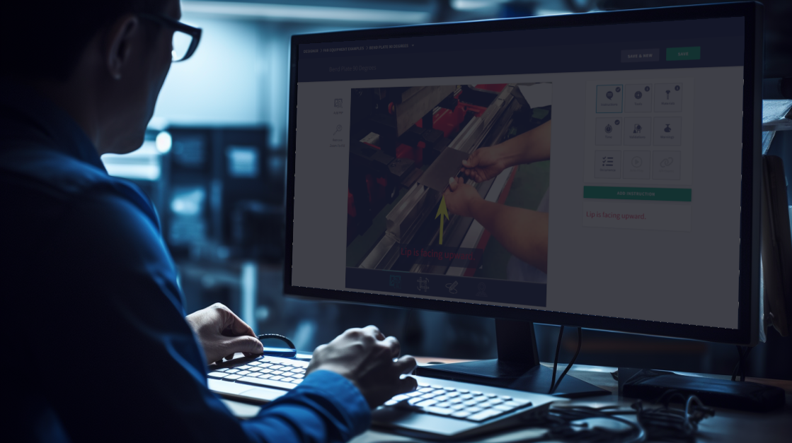
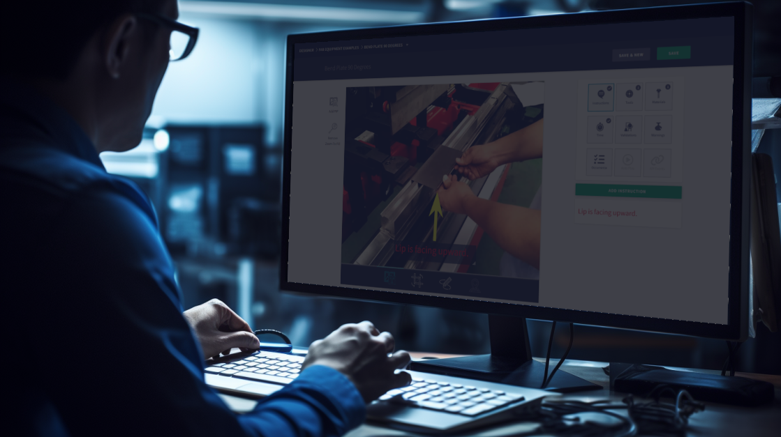
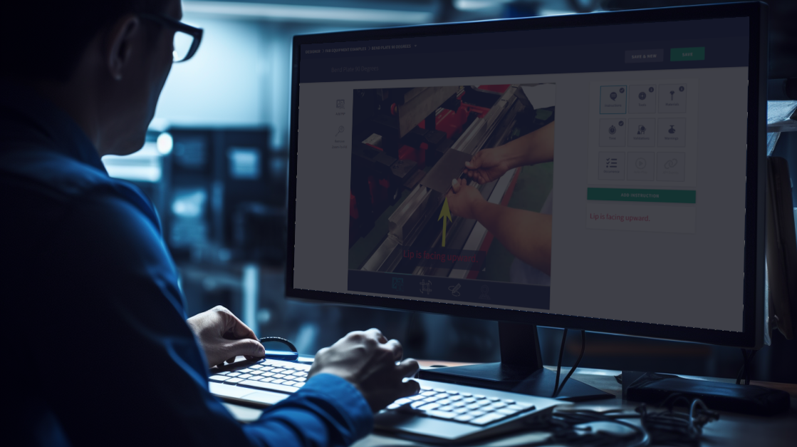
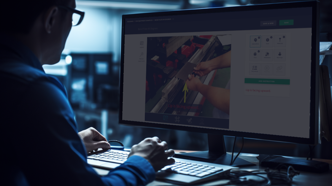
Inside the Step Editor, to the right of the Step Image, you will find 9 tiles. Each tile represents additional methods to enhance your Digital Work Instructions further. These tiles provide a range of options and tools that enable you to create comprehensive and visually engaging instructions, ensuring a smooth and efficient workflow on the production floor.
Instructions
To add Text Instructions select the top-left tile and press the green button below "ADD INSTRUCTION".

With the editor open, you can type in your instructions while editing the text size and colors. Once the text is ready, press the "COMPLETE" button to have it generate on the Step Image.

The Text Instruction will be displayed at the top-left of the Step Image in the Step Editor. To resize the text box, click on the bottom-right corner of the text box and adjust its size as needed. Additionally, you can click and drag the text box to place it in the desired location within the Step Image.
To Edit or Delete an existing Text Instruction hover over the box on the right side of the screen, below the 9 tiles. A pencil (Edit) and trashcan (Delete) icon will appear.
To add multiple Text Instructions to a single step, press "ADD INSTRUCTION".
Tools
For Steps that require the usage of a Tool, it is recommended to embed the tool directly into the Step. To access your Tool Library, click on the "Tools" tile located at the top-center of the tile grid. From there, click on "ADD TOOL" to open the Select Tool Module.

If you have existing Tools in your library, they will appear on the Select Tool Screen. You can simply click on the Tools needed for this Step and press "ADD TOOLS" to embed them into the Step.
In case the required Tool does not exist in the library, you can create a new one by clicking on "CREATE NEW TOOL" and providing the relevant details.

Once a Tool is embedded to the Work Instruction, you can click on the Tool to add Step specific details.
Materials
One of the significant benefits of using Digital Work Instructions is that your operators can easily access the precise Tools & Materials required for individual Steps, eliminating the need to rely on a top-level list. To assign Materials to a Step, simply click on the "Materials" icon located at the top-right of the tile grid, and then click the "ADD MATERIAL" button.

Include the Material Name (or Description), the Part Number, and an integer value to represent the Quantity. When satisfied, press "COMPLETE".
Example: 3.5" of Red Wire (Quantity 1)
Time
Each Step can have a pre-determined allocated time, which serves to inform the operators when the task should be nearing completion. When 80% of the allocated time has elapsed, the timers will change to Alert Orange, providing a visual indication of the approaching deadline.

If a Step does not have an assigned time, the timers will also be displayed as Alert Orange. However, it is strongly recommended that you utilize a time, even if it's just an estimate, to help operators distinguish the importance of the two colors. This distinction aids operators in understanding the urgency and importance of each step, promoting better time management and overall efficiency in the production process.

To allocate a Time to a Step, simply click on the 4th tile labeled "Time" in the tile grid. This action will present you with options to select the hours, minutes, and seconds needed to complete the Step.
Warnings
An effective approach to prevent common defects or injuries is by embedding a Warning to a Step. To access Warnings, click on the 6th tile labeled "Warnings" in the tile grid, and then simply press the "ADD WARNING" button.

Here, you will be able to set Safety and/or Defect Warnings (1 of each max per step). You can determine how frequent the Warning will appear, describe the concern, and if desired include a photo.
In Compass, Warnings will be displayed at the beginning of a Step, and Operators will be prompted to acknowledge and close the Notice, ensuring that they have seen and understood the Warning message. This feature helps to ensure that critical safety information or important instructions are properly communicated to the Operators, reducing the likelihood of overlooking crucial details and enhancing overall safety and compliance during the production process.
Saving Step Changes
When you are done making changes to the Step, be sure to Save your work. At the top-right hand side of the Step Editor page, you will see "SAVE & NEW" and "SAVE".

- SAVE & NEW: Will save all changes, and open a new blank Step
- SAVE: Will save all changes, and will return to Unit parent-level


Basic Step Instructions
In this training session we will review Setup and uploading images to Work Instructions in HQ Designer. Before proceeding with this training, please ensure that you have completed Designer Part 2 ('Creating A Unit'). This training assumes that you already have a Unit set up in the system.
Setup Instructions

In Compass, the production floor application, an essential feature is the ability to auto-compile all the Tools and Materials used in a Work Instruction. These compiled tools and materials are then displayed in the Setup Details page for easy reference and accessibility.
On the right side of the Setup Details page, you will find a section titled "DETAILS." This section contains multiple images and accompanying text.

To create or make changes to the Setup Instructions, click on the down-arrow and select "SETUP". This will open the Setup Details Module.

In the Setup Details Module, you have the option to enhance the Work Instruction by uploading images and corresponding text. These visuals and descriptions are designed to assist operators in preparing for the production run.
To save the changes you've made in the Setup Details, simply click on the "SAVE" button. If you have multiple instructions that you want to include in the Setup Details, you can press the "ADD DETAIL" button. This allows you to add additional images and accompanying text to cover various aspects of the setup procedure comprehensively.
ADD Step
Work Instructions are constructed using individual Steps, which represent the specific actions required of your production staff. To create a Step and access the editor, click on "ADD STEP" from the ADD Menu.

Naming Step
When you create Steps, they are initially generated with default names such as "Untitled Step #1", "Untitled Step #2", and so on. To change the name of the step click on the name and it will become editable.
It is highly recommended that you rename these Steps to match the specific tasks they represent. Providing meaningful names to the Steps can be incredibly useful when reviewing Production Reports.
Selecting Step Image
To add an image to the Step, drag the file from the known folder on your computer, or click on the large image tile and browse for it instead.

When you assign an image to a Step in the Work Instructions, additional features become available. Clicking the image will engage it, offering options to DELETE or REPLACE the image when hovering over it. To disengage the image, click anywhere on the image, excluding the two buttons.
Zoom-To-Fill

Standard Step images have a 5:4 ratio. If the image you selected does not match this ratio, you may encounter white space either on the left/right side or top/bottom of the image. To resolve this, you can use the "Zoom-To-Fill" button. When you press this button, the image will be enlarged to fit the Step perfectly, ensuring no white space is shown and providing a visually appealing presentation of the image within the Step.
Picture-in-Picture (PIP)
For more complex Steps, you can use multiple images by utilizing Picture-in-Picture (PIP) functionality. At the top-left of the Image Tile, you will find a button named "Add PIP." Clicking this button will create a new image layer and allow you to load another image.

You can add multiple PIPs to a single Step, and these PIPs can even be in the form of video files (up to 40 MB in size). Clicking on a PIP will engage it, providing options to 'DELETE' or 'REPLACE' the image, similar to the main Step Image.
Crop and Rotate Image

Below the Step Image, you will notice 4 icons. Clicking on the 2nd icon from the left will switch the tool to Crop and Rotate mode. Once engaged, 3 new icons will appear on the left side of the Step Image. You can use Rotate Left or Right to rotate the image by 90 degrees. To crop the image, simply click on any perimeter of the image and move it to the desired location. Remember to press the Save icon on the left side to save your changes.
Drawing Editor

When you click on the 3rd icon from the left, located below the Step Image, the tool will switch to the Drawing Editor. With this feature engaged, you gain the ability to draw directly on your main image. To the left of the Step Image, you can select the shape you intend to use for your drawing. Above the Step Image, you will find options to specify the colors and weights of the shapes you draw. This powerful drawing tool enables you to annotate your images and add important visual cues or notes directly to the Step, enhancing the clarity and comprehensiveness of your Work Instructions.

When you are done Drawing over your image, you must exit the Drawing Editor to make further changes. To do this either click far left icon below the Step Image (Image/Text Editing) or move your mouse to the right of the Step Image and click "Exit Drawing".


Creating a Unit
During this training, we will walk you through the steps required to create a new Unit and navigating your editable options. Units serve as the parent group of Work Instructions and typically represent the Engineering Number of the product being constructed.
Create Unit

Locate the "CREATE UNIT" button on the left side of the Secondary Navigation. Click on this button to access the module for creating a new set of Work Instructions. This will open up the necessary interface to begin the process of creating your Unit.

Before you proceed with creating Digital Work Instructions, it is essential to have your Work Areas configured in your HQ Account. Work Instructions are organized and categorized based on Work Areas, and selecting the appropriate Work Area is the first step to get started with creating your instructions. Make sure you have set up the relevant Work Areas in your HQ Account before proceeding with the Work Instruction creation process.

Once you have chosen the desired Work Area, the next step is to set the Unit Name and Revision Number for the Work Instruction you are creating. The Unit Name typically corresponds to the Engineering Number of the product being constructed. On the other hand, the Revision Number should align with the Engineering Revision Number associated with the product.

The last optional task is to upload an image that will be associated with the top-level Work Instruction. This image is commonly a photo of the final customer-facing product. Please note that the image will only appear in the navigation of Designer and on the Unit Assigned screen of Compass.
When you have finished setting up the Unit Name, Revision Number, and optionally uploading an image, click on the "COMPLETE" button. This action will take you to the Parent Level editor, where you can start creating and editing your Digital Work Instructions for the selected Unit.
Parent Level Navigation

In the image provided, we have created a Unit named "Tutorial Example" with the Revision Number "REV 1." Along with this, our account shows three distinct Station Types: Workbench, Tester, and Packaging (please note that the specific Station Types may vary depending on your setup).
ADD Menu

Station Types serve a crucial purpose on the production floor in Compass. Each Compass station is assigned a unique Station Type, which helps the Compass station retrieve the correct set of documents associated with that particular task or production cell.
To the right of each Station Type you will see "ADD STEP" and a down-arrow, this ADD Menu will give you access to tools or folders to populate the digital files associated with the Unit.
Change Unit Name

To update the top-level Name of a Unit, click on the Unit name at the top of the screen. This action will change the display from read-only to editable. Modify the Unit name as needed. After making the desired changes, click anywhere outside of the textbox to save the updated Unit Name.
Change Unit Revision

To update the top-level Revision of a Unit, locate the gray box situated to the right of the Unit name at the top of the screen. Click on the gray box and it will open the Revision Change module.

Once the module is opened, you will be able to make the necessary adjustments. Press 'OK' to save the change, or 'Cancel' to close module.


Designer Basics
In this training we will be reviewing HQ Designer, the application responsible for creating, editing, and managing all Digital Work Instructions.
Accessing Designer

Before accessing the application, ensure that you have an HQ account with the Designer App Access enabled under HQ Admin Users. If you already have an account, you can proceed to use the application by following these steps:
- Go to https://hq.scout.systems in your web browser.
- Sign in using the same Email address and Password that you used when creating your HQ account.
To access the Designer section, click on the green button located in the top-left corner of the application. From the dropdown menu that appears, select "Designer". This will take you to the top-level of Designer.
Navigating Designer

Once you are in the Designer section, you will notice a secondary navigation bar. Look for the words "ALL ACTIVE" which will be underlined. Clicking on this option will allow you to view all existing Work Instructions.
To further refine your view, locate the "WORK AREAS" section on the right side of the navigation bar. By clicking on this option, you can isolate instructions specific to an individual Work Area, making it easier to focus on the relevant information.

Underneath the secondary navigation are additional display options to support Filtering and Searching for existing Digital Work Instructions.
- SORT: Use this dropdown to easily reorder all instructions based on your preference.
- FILTER: Work Instructions often have multiple stages. With this option, you can isolate Work Instructions to view specific stages according to your requirements.
- COLLECTION: Organize Work Instructions into custom-made Collections. Use this dropdown to display only the Work Instructions in the desired Collection.
- SHOW: Limit the number of Work Instructions loaded on the page for easier navigation and improved performance.

To the far right of the Display Options is a magnifying glass icon; click on that to open a search bar.